


 Sun4Schools Curriculum
The Power of Solar Energy
Lesson 6 ~ What is Photovoltaics?
Objectives
Background
Activity 1: The Effect of Solar Energy on Light or Electrical Output
Wrap-up
Objectives
- Students will describe how photovoltaic (PV) systems convert sunlight to electricity
- Students will identify PV system components
- Students will understand the factors that contribute to the efficiency of a PV system
- Students will demonstrate the effect of solar energy on electrical output
Background
Photovoltaic (PV) systems convert sunlight into electricity. The photovoltaic effect is the basic physical process through which this happens. Sunlight is composed of photons, or particles of solar energy. These photons contain various amounts of energy corresponding to the different wavelengths of the solar spectrum. When photons strike a PV cell, they may be reflected or absorbed, or they may pass right through. Only the absorbed photons generate electricity. When this happens, the energy of the photon is transferred to an electron in an atom of the cell (which is actually a semiconductor). With its newfound energy, the electron is able to escape from its normal position associated with that atom to become part of the current in an electrical circuit. By leaving this position, the electron causes a "hole" to form. Special electrical properties of the PV cell-a built-in electric field-provide the voltage needed to drive the current through an external load (such as a light bulb).
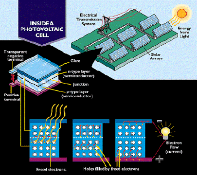
Source: Utility Photovoltaic Group
In order for the photovoltaic effect to occur efficiently, a potential installation site must meet certain requirements, including:
- Orientation: the building must have a southern exposure. For maximum daily power output, the installed PV modules must face due south (180 degrees), plus or minus 30 degrees (i.e., 150-210 degrees) and be exposed to the sun for as much of the day as possible, especially during the peak hours of 9 a.m. to 3 p.m.
- Shading: Significant shading from trees, buildings, mountains, and other obstructions on the roof between 3 hours before and after solar noon will reduce solar energy collection. Solar noon is the midpoint between sunrise and sunset times.
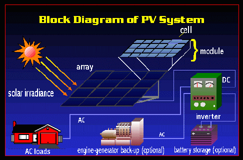
A PV system comprises several components. The basic building block of a PV panel is the PV cell, which is a solid state, or non-mechanical, device. A solar system uses a number of PV panels, each made of silicon, plus boron and phosphorous. The output of a single cell under direct sunlight is about one watt. To increase their effectiveness, dozens of individual cells are interconnected together in a sealed, weatherproof glass package called a module. Modules come in a range of wattages, and their nature allows for great flexibility in designing systems that meet a variety of electrical needs.
Since PV modules are only capable of producing direct current (DC) electricity, an inverter is required to convert the direct current (DC) output produced by the PV array into alternating current (AC) power. AC electricity is needed to run computers, refrigerators and other appliances, and lighting.
A utility-intertied-sometimes called grid-connected-PV system, such as those installed under the Sun4Schools project, generate electricity which is supplemented by the energy provided by the existing utility grid. A utility-intertied PV system requires neither battery storage nor an emergency back-up system since it is connected directly to the utility grid, which is used as the storage medium. Systems that are not connected to the utility grid use batteries to store energy for use when the sun is not shining. While a utility-intertied PV system can be designed to provide all of a building's electrical needs, most systems provide only a portion of the total electricity requirements.
A well-designed and properly installed PV system with a consistent maintenance schedule will operate for more than 20 years. The PV module, which has no moving parts, has an expected lifetime of more than 30 years.
Source: Utility Photovoltaic Group
The Effect of Solar Energy on Light or Electrical Output
(Source: Utah State Science)
Solar energy can be measured directly (if connected to a voltmeter) or indirectly (by noting light output when cells are wired to a small light bulb). Demonstrate how reducing solar input reduces current voltage and, in turn, reduces light output.
Teacher's Notes: Caution students to perform this experiment carefully by ensuring that all connections are secure. Students should handle all materials carefully to prevent breakage.
Materials:
- Three or more solar cells* (Note: Students will need three 0.5-volt solar cells to make a 1.5-volt light work correctly)
- Short lengths of 22-gauge wire
- Four to six small alligator clips
- One small LED flashlight bulb OR one voltmeter capable of measuring voltages below 1.5 volts*
- Several pieces of cellophane of various colors, large enough to cover all solar cells when they are wired to form a simple circuit
- Screening of different mesh sizes and materials, large enough to cover all solar cells **
- Wax paper or other transparent material, large enough to cover all solar cells Glass plate, clear plastic wrap, or other clear material, large enough to cover all solar cells
- Sunny room or area in which to place circuit
*available from electronic components stores, solar equipment dealers, or catalogs (a list of Montana solar equipment dealers is located here.)
**available from craft stores or floral shops
Method:
- Have students wire a simple circuit in series-connected end to end so that the current through each is the same. To wire the circuit in series, use the alligator clips to connect the three solar cells as follows:
- Connect the negative (black) lead from cell #1 to the positive (red) lead of cell #2.
- Connect the negative (black) lead from cell #2 to the positive (red) lead of cell #3.
- Connect the negative (black) lead from cell #3 to the negative (black) lead of the light or voltmeter.
- Connect the positive (red) lead from the voltmeter or light to the negative (black) lead of cell #1.
- When the light or voltmeter is working correctly, experiment with each cover material (colored cellophane, screening, wax paper, glass or clear plastic) and record the effects of each material on the light or voltage output.
Wrap-up
Lead a class discussion on why different materials might affect output. Student might observe, for example, that darker colors reduce available sunlight reaching the solar cells and thus reduce output. Screening with larger mesh allows more sunlight to pass through to the solar cells than smaller mesh. How might this concept be applied to the effect of clouds or shading on PV system output?
» Next Section: Lesson 7 ~ How is PV Used?
« Back to Solar Projects Page